How to Draw Line in Microstation
 We will start discussing details on our drawing tools. We are going to discuss some basic drawing tools, and how to use it with tool settings. The basic elements are linear, circle, and polygon elements.
Using tool settings
We use tool settings to change the element parameters. Tool settings will show you all available parameter for active tool. When you activate place circle, it will show you parameters for circle. When you activate place line, it will show you all parameters for line. Not just for drawing, it's also used for modify and view navigation tools.
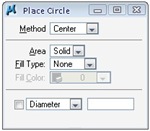
Activate place circle and take a look at the tool settings for circle. You can see that there is a diameter parameter. But if you have been playing with MicroStation tools for a while, you'll find out that you don't need to input diameter when placing circle. You can simply use AccuDraw to place two data points. So how can tool settings and AccuDraw can work together?
They talk to each other. Let's try to activate place circle from navigation bar. Place a data point anywhere on your screen as the circle center point. Now move your pointer. As we have discussed before, the value in AccuDraw will be updated instantly. You can move your pointer, type the radius, and click data point to place the circle. But don't define the second data point yet! See your tool settings. The diameter value is also changing.
Click reset to cancel this circle placement. Now, with the place circle still active, lock the diameter value in your tool settings, and type the diameter value.
![]()
Move your pointer to drawing area. Now you can see a circle attached to your pointer! If you defined the diameter (or radius) before defining data point, you can click only once to place the circle. Very useful if you have to place many circle with the same radius.
Linear Elements
We will discuss more about circle later. Now, let's discuss about linear elements.

Place SmartLine
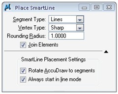
We've been using SmartLine a couple of times. It's named SmartLine, but we can place several elements type just using this tool. The elements can be:
- Line, if it only has one line segment
- Arc, if it only has one arc segment
- Line string, if it has several line segments
- Complex chain, if it has several line and arc segments
- Complex shape, if it's a closed element
A SmartLine can have arc and lines. You can change the segment type from line to arc and vice versa during placing the element. You can also change the vertex type to rounded or chamfered.

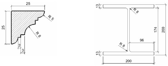
A little tip: You can quickly change the top most parameter in tool settings by pressing [~] in your keyboard. See the animation for creating the profile below.

You can download an old animation here. They will show you how those profile were created. I created it using a free recorder when I still use V8 XM. Yes, it's executable files, they have their own player.
Place Line
Another linear element that we can consider as basic is 'place element'. You only can place a simple line using this tool. Every line you created only has one segment. You create four line segments, then it will be four separate lines.
Let's take a look at the tool settings. There are only two parameters: length and angle. Try to lock the value for these two before you place your line.

What happen? You only need to place one data point, and it already has the length and angle you wanted!
I work as a Sr. Technical Consultant in Tech Data Advanced Solutions Indonesia. I've been using AutoCAD since R14 and Revit since Revit Building 9. I occasionally write for AUGIWorld magazine and also active in Autodesk discussion forum.
I'm an Autodesk Certified Professional (ACP) for Revit Architecture and AutoCAD. I'm also a member of Autodesk Expert Elite, appreciation for individuals who give contribution to Autodesk community.
Connect with me on twitter or LinkedIn
How to Draw Line in Microstation
Source: https://www.cad-notes.com/using-tool-settings-and-linear-elements/
0 Response to "How to Draw Line in Microstation"
Enviar um comentário